Raw TikZ
tikzfigure covers the most common TikZ operations through its Python API, but
TikZ is a vast language. fig.raw(string) injects an arbitrary LaTeX/TikZ
snippet directly into the generated code - giving you a full escape hatch.
A key pattern: create nodes with the Python API (to get auto-generated labels),
then reference them in raw TikZ commands via {node.label}.
This tutorial covers: - basic raw insertion - flowcharts with decision diamonds
- mathematical annotations and axis drawing - network graphs with curved edges - PDF animations - timeline visualizations
import math
from tikzfigure import TikzFigure
Basic raw insertion
Section titled “Basic raw insertion”Pass any TikZ string to raw. Node labels created by node can be interpolated
into the string.
fig = TikzFigure()
n1 = fig.node(    (0, 0),    shape="circle",    color="white",    fill="blue",    content="Hello!",)n2 = fig.node(    (5, 0),    shape="circle",    color="white",    fill="red",    content="Hi!",)
# A raw commentfig.raw("% --- raw TikZ below ---")
# A plain text node at a fixed coordinatefig.raw(    "\\node at (2.5, 1.2) {raw TikZ node};",)
# A dashed arrow referencing the Python-created node labelsfig.raw(    f"\\draw[->, thick, dashed] ({n2.label}) -- ({n1.label});",)
fig.show()
/home/runner/work/tikzfigure/tikzfigure/.venv/lib/python3.12/site-packages/fitz/__init__.py:17: FutureWarning: The `fitz` API is deprecated and will be removed in future. Use `import pymupdf` instead. warnings.warn(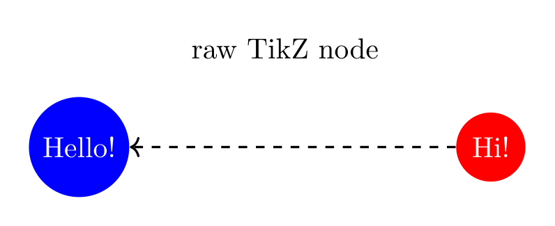
Show the TikZ code
% --------------------------------------------- %% Tikzfigure generated by tikzfigure v0.5.0 %% https://github.com/max-models/tikzfigure %% --------------------------------------------- %\begin{tikzpicture} \node[shape=circle, color=white, fill=blue] (node0) at ({0}, {0}) {Hello!}; \node[shape=circle, color=white, fill=red] (node1) at ({5}, {0}) {Hi!}; % --- raw TikZ below --- \node at (2.5, 1.2) {raw TikZ node}; \draw[->, thick, dashed] (node1) -- (node0);\end{tikzpicture}Show the standalone LaTeX document
\documentclass[border=10pt]{standalone}\PassOptionsToPackage{dvipsnames,svgnames,x11names}{xcolor}\usepackage{tikz}\usepackage{pgfplots}\pgfplotsset{compat=newest}\usepgfplotslibrary{groupplots}\usetikzlibrary{arrows.meta}\begin{document}% --------------------------------------------- %% Tikzfigure generated by tikzfigure v0.5.0     %% https://github.com/max-models/tikzfigure      %% --------------------------------------------- %\begin{tikzpicture}    \node[shape=circle, color=white, fill=blue] (node0) at ({0}, {0}) {Hello!};    \node[shape=circle, color=white, fill=red] (node1) at ({5}, {0}) {Hi!};    % --- raw TikZ below ---    \node at (2.5, 1.2) {raw TikZ node};    \draw[->, thick, dashed] (node1) -- (node0);\end{tikzpicture}
\end{document}
Flowchart
Section titled “Flowchart”Flowcharts need diamond decision nodes and labelled arrows - both easy with
raw TikZ.
fig = TikzFigure()fig.usetikzlibrary("shapes.geometric")
start = fig.node(    (2, 4),    shape="ellipse",    fill="green!30",    content="Start",)process = fig.node(    (2, 2),    shape="rectangle",    fill="blue!20",    content="Process",)decision = fig.node(    (2, 0),    shape="diamond",    fill="orange!30",    content="Decision?",)yes_node = fig.node(    (0, -2),    shape="rectangle",    fill="red!20",    content="Action A",)no_node = fig.node(    (4, -2),    shape="rectangle",    fill="green!20",    content="Action B",)end = fig.node(    (2, -4),    shape="ellipse",    fill="red!30",    content="End",)
fig.raw(    f"\\draw[->, thick] ({start.label})    -- ({process.label});",)fig.raw(    f"\\draw[->, thick] ({process.label})  -- ({decision.label});",)fig.raw(    f"\\draw[->, thick] ({decision.label}) -- node[left]  {{Yes}} ({yes_node.label});",)fig.raw(    f"\\draw[->, thick] ({decision.label}) -- node[right] {{No}}  ({no_node.label});",)fig.raw(    f"\\draw[->, thick] ({yes_node.label}) -- ({end.label});",)fig.raw(    f"\\draw[->, thick] ({no_node.label})  -- ({end.label});",)
fig.show()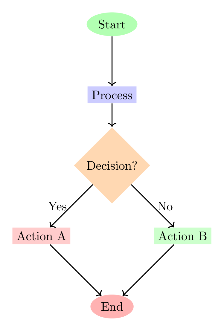
Show the TikZ code
% --------------------------------------------- %% Tikzfigure generated by tikzfigure v0.5.0 %% https://github.com/max-models/tikzfigure %% --------------------------------------------- %\begin{tikzpicture} \node[shape=ellipse, fill=green!30] (node0) at ({2}, {4}) {Start}; \node[shape=rectangle, fill=blue!20] (node1) at ({2}, {2}) {Process}; \node[shape=diamond, fill=orange!30] (node2) at ({2}, {0}) {Decision?}; \node[shape=rectangle, fill=red!20] (node3) at ({0}, {-2}) {Action A}; \node[shape=rectangle, fill=green!20] (node4) at ({4}, {-2}) {Action B}; \node[shape=ellipse, fill=red!30] (node5) at ({2}, {-4}) {End}; \draw[->, thick] (node0) -- (node1); \draw[->, thick] (node1) -- (node2); \draw[->, thick] (node2) -- node[left] {Yes} (node3); \draw[->, thick] (node2) -- node[right] {No} (node4); \draw[->, thick] (node3) -- (node5); \draw[->, thick] (node4) -- (node5);\end{tikzpicture}Show the standalone LaTeX document
\documentclass[border=10pt]{standalone}\PassOptionsToPackage{dvipsnames,svgnames,x11names}{xcolor}\usepackage{tikz}\usepackage{pgfplots}\pgfplotsset{compat=newest}\usepgfplotslibrary{groupplots}\usetikzlibrary{arrows.meta,shapes.geometric}\begin{document}% --------------------------------------------- %% Tikzfigure generated by tikzfigure v0.5.0     %% https://github.com/max-models/tikzfigure      %% --------------------------------------------- %\begin{tikzpicture}    \node[shape=ellipse, fill=green!30] (node0) at ({2}, {4}) {Start};    \node[shape=rectangle, fill=blue!20] (node1) at ({2}, {2}) {Process};    \node[shape=diamond, fill=orange!30] (node2) at ({2}, {0}) {Decision?};    \node[shape=rectangle, fill=red!20] (node3) at ({0}, {-2}) {Action A};    \node[shape=rectangle, fill=green!20] (node4) at ({4}, {-2}) {Action B};    \node[shape=ellipse, fill=red!30] (node5) at ({2}, {-4}) {End};    \draw[->, thick] (node0)    -- (node1);    \draw[->, thick] (node1)  -- (node2);    \draw[->, thick] (node2) -- node[left]  {Yes} (node3);    \draw[->, thick] (node2) -- node[right] {No}  (node4);    \draw[->, thick] (node3) -- (node5);    \draw[->, thick] (node4)  -- (node5);\end{tikzpicture}
\end{document}
Mathematical annotations and coordinate axes
Section titled “Mathematical annotations and coordinate axes”Raw TikZ handles axis arrows, tick marks, parabolas, and LaTeX math ($...$)
naturally.
fig = TikzFigure()
p1 = fig.node((0, 0), content="")p2 = fig.node((3, 2), content="")p3 = fig.node((6, 0), content="")
fig.raw(    f"\\draw[thick, blue] ({p1.label}) parabola bend ({p2.label}) ({p3.label});",)fig.raw(    f"\\draw[->, dashed, red] ({p1.label}) -- ({p2.label}) node[midway, left=40pt] {{$\\Delta y$}};",)fig.raw(    f"\\draw[->, dashed, green!50!black] ({p1.label}) -- ({p3.label}) node[midway, below=10pt] {{$\\Delta x$}};",)fig.raw(    "\\node at (3, 3) {$y = ax^2 + bx + c$};",)
fig.raw(    "\\draw[->, thick] (-1, 0) -- (7, 0) node[right] {$x$};",)fig.raw(    "\\draw[->, thick] (0, -1) -- (0, 3.5) node[above] {$y$};",)
for i in range(1, 7):    fig.raw(        f"\\draw ({i}, -0.1) -- ({i}, 0.1) node[below=3pt] {{\\small {i}}};",    )
fig.show()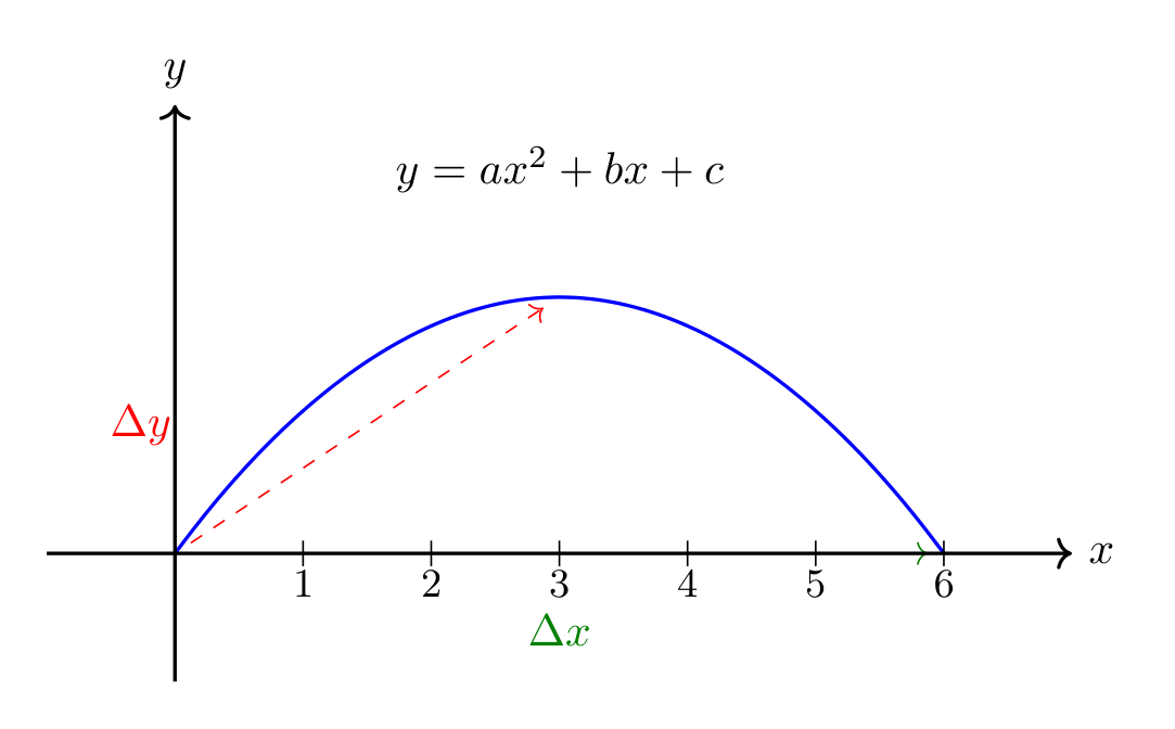
Show the TikZ code
% --------------------------------------------- %% Tikzfigure generated by tikzfigure v0.5.0 %% https://github.com/max-models/tikzfigure %% --------------------------------------------- %\begin{tikzpicture} \node (node0) at ({0}, {0}) {}; \node (node1) at ({3}, {2}) {}; \node (node2) at ({6}, {0}) {}; \draw[thick, blue] (node0) parabola bend (node1) (node2); \draw[->, dashed, red] (node0) -- (node1) node[midway, left=40pt] {$\Delta y$}; \draw[->, dashed, green!50!black] (node0) -- (node2) node[midway, below=10pt] {$\Delta x$}; \node at (3, 3) {$y = ax^2 + bx + c$}; \draw[->, thick] (-1, 0) -- (7, 0) node[right] {$x$}; \draw[->, thick] (0, -1) -- (0, 3.5) node[above] {$y$}; \draw (1, -0.1) -- (1, 0.1) node[below=3pt] {\small 1}; \draw (2, -0.1) -- (2, 0.1) node[below=3pt] {\small 2}; \draw (3, -0.1) -- (3, 0.1) node[below=3pt] {\small 3}; \draw (4, -0.1) -- (4, 0.1) node[below=3pt] {\small 4}; \draw (5, -0.1) -- (5, 0.1) node[below=3pt] {\small 5}; \draw (6, -0.1) -- (6, 0.1) node[below=3pt] {\small 6};\end{tikzpicture}Show the standalone LaTeX document
\documentclass[border=10pt]{standalone}\PassOptionsToPackage{dvipsnames,svgnames,x11names}{xcolor}\usepackage{tikz}\usepackage{pgfplots}\pgfplotsset{compat=newest}\usepgfplotslibrary{groupplots}\usetikzlibrary{arrows.meta}\begin{document}% --------------------------------------------- %% Tikzfigure generated by tikzfigure v0.5.0     %% https://github.com/max-models/tikzfigure      %% --------------------------------------------- %\begin{tikzpicture}    \node (node0) at ({0}, {0}) {};    \node (node1) at ({3}, {2}) {};    \node (node2) at ({6}, {0}) {};    \draw[thick, blue] (node0) parabola bend (node1) (node2);    \draw[->, dashed, red] (node0) -- (node1) node[midway, left=40pt] {$\Delta y$};    \draw[->, dashed, green!50!black] (node0) -- (node2) node[midway, below=10pt] {$\Delta x$};    \node at (3, 3) {$y = ax^2 + bx + c$};    \draw[->, thick] (-1, 0) -- (7, 0) node[right] {$x$};    \draw[->, thick] (0, -1) -- (0, 3.5) node[above] {$y$};    \draw (1, -0.1) -- (1, 0.1) node[below=3pt] {\small 1};    \draw (2, -0.1) -- (2, 0.1) node[below=3pt] {\small 2};    \draw (3, -0.1) -- (3, 0.1) node[below=3pt] {\small 3};    \draw (4, -0.1) -- (4, 0.1) node[below=3pt] {\small 4};    \draw (5, -0.1) -- (5, 0.1) node[below=3pt] {\small 5};    \draw (6, -0.1) -- (6, 0.1) node[below=3pt] {\small 6};\end{tikzpicture}
\end{document}
Network graph with curved edges
Section titled “Network graph with curved edges”Nodes placed in a ring with bend left edges and some cross-connections.
fig = TikzFigure()
n = 6R = 3nodes = []for i in range(n):    angle = 360 / n * i    x = R * math.cos(math.radians(angle))    y = R * math.sin(math.radians(angle))    nodes.append(        fig.node(            x,            y,            shape="circle",            fill="cyan!40",            content=f"N{i}",        ),    )
# Ringfor i in range(n):    j = (i + 1) % n    fig.raw(        f"\\draw[->, thick, bend left=15] ({nodes[i].label}) edge ({nodes[j].label});",    )
# Cross-connectionsfig.raw(    f"\\draw[->, red,              thick, dashed, bend right=30] ({nodes[0].label}) edge ({nodes[3].label});",)fig.raw(    f"\\draw[->, blue,             thick, dotted, bend left=30]  ({nodes[1].label}) edge ({nodes[4].label});",)fig.raw(    f"\\draw[->, green!60!black,   thick,         bend right=30] ({nodes[2].label}) edge ({nodes[5].label});",)
fig.raw(    "\\node[font=\\Large\\bfseries] at (0, 4.5) {Network Graph};",)
fig.show()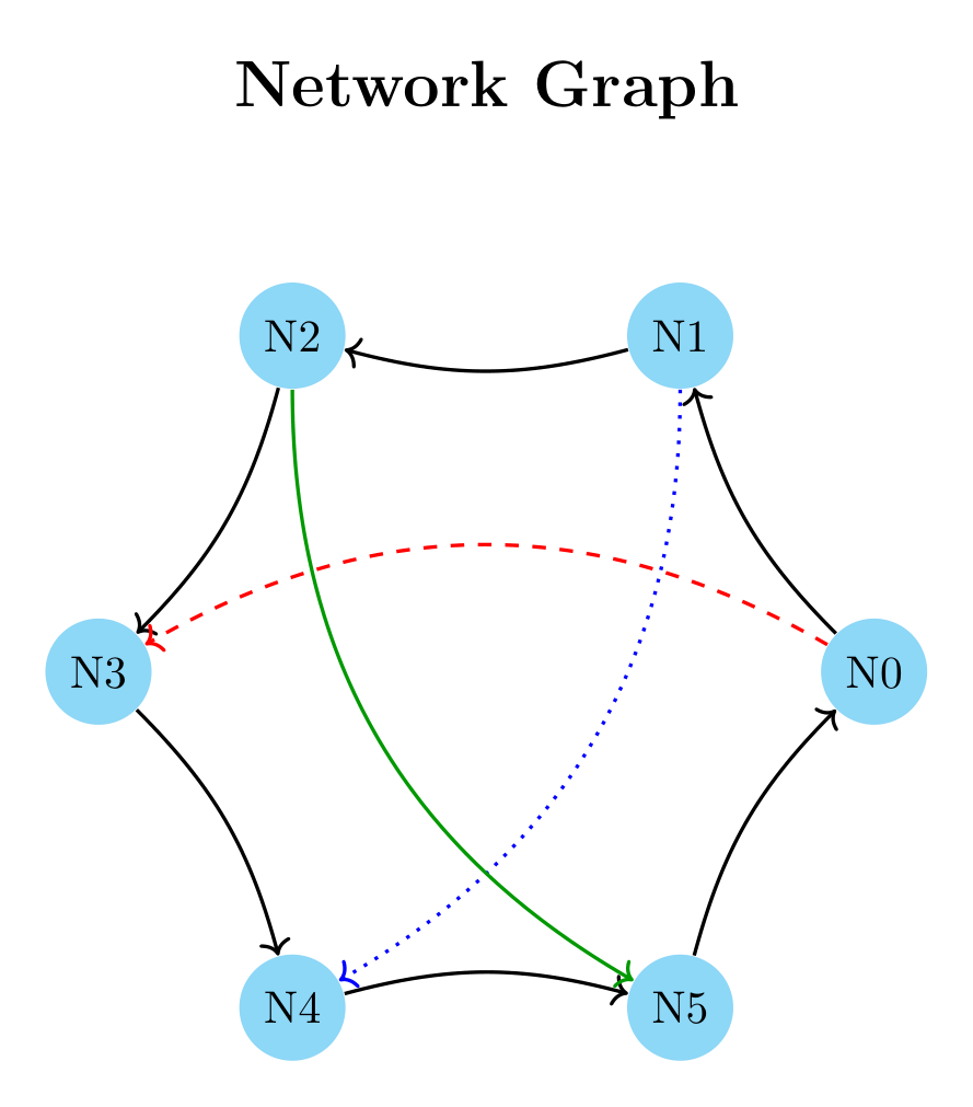
Show the TikZ code
% --------------------------------------------- %% Tikzfigure generated by tikzfigure v0.5.0 %% https://github.com/max-models/tikzfigure %% --------------------------------------------- %\begin{tikzpicture} \node[shape=circle, fill=cyan!40] (node0) at ({3.0}, {0.0}) {N0}; \node[shape=circle, fill=cyan!40] (node1) at ({1.5000000000000004}, {2.598076211353316}) {N1}; \node[shape=circle, fill=cyan!40] (node2) at ({-1.4999999999999993}, {2.598076211353316}) {N2}; \node[shape=circle, fill=cyan!40] (node3) at ({-3.0}, {3.6739403974420594e-16}) {N3}; \node[shape=circle, fill=cyan!40] (node4) at ({-1.5000000000000013}, {-2.598076211353315}) {N4}; \node[shape=circle, fill=cyan!40] (node5) at ({1.5000000000000004}, {-2.598076211353316}) {N5}; \draw[->, thick, bend left=15] (node0) edge (node1); \draw[->, thick, bend left=15] (node1) edge (node2); \draw[->, thick, bend left=15] (node2) edge (node3); \draw[->, thick, bend left=15] (node3) edge (node4); \draw[->, thick, bend left=15] (node4) edge (node5); \draw[->, thick, bend left=15] (node5) edge (node0); \draw[->, red, thick, dashed, bend right=30] (node0) edge (node3); \draw[->, blue, thick, dotted, bend left=30] (node1) edge (node4); \draw[->, green!60!black, thick, bend right=30] (node2) edge (node5); \node[font=\Large\bfseries] at (0, 4.5) {Network Graph};\end{tikzpicture}Show the standalone LaTeX document
\documentclass[border=10pt]{standalone}\PassOptionsToPackage{dvipsnames,svgnames,x11names}{xcolor}\usepackage{tikz}\usepackage{pgfplots}\pgfplotsset{compat=newest}\usepgfplotslibrary{groupplots}\usetikzlibrary{arrows.meta}\begin{document}% --------------------------------------------- %% Tikzfigure generated by tikzfigure v0.5.0     %% https://github.com/max-models/tikzfigure      %% --------------------------------------------- %\begin{tikzpicture}    \node[shape=circle, fill=cyan!40] (node0) at ({3.0}, {0.0}) {N0};    \node[shape=circle, fill=cyan!40] (node1) at ({1.5000000000000004}, {2.598076211353316}) {N1};    \node[shape=circle, fill=cyan!40] (node2) at ({-1.4999999999999993}, {2.598076211353316}) {N2};    \node[shape=circle, fill=cyan!40] (node3) at ({-3.0}, {3.6739403974420594e-16}) {N3};    \node[shape=circle, fill=cyan!40] (node4) at ({-1.5000000000000013}, {-2.598076211353315}) {N4};    \node[shape=circle, fill=cyan!40] (node5) at ({1.5000000000000004}, {-2.598076211353316}) {N5};    \draw[->, thick, bend left=15] (node0) edge (node1);    \draw[->, thick, bend left=15] (node1) edge (node2);    \draw[->, thick, bend left=15] (node2) edge (node3);    \draw[->, thick, bend left=15] (node3) edge (node4);    \draw[->, thick, bend left=15] (node4) edge (node5);    \draw[->, thick, bend left=15] (node5) edge (node0);    \draw[->, red,              thick, dashed, bend right=30] (node0) edge (node3);    \draw[->, blue,             thick, dotted, bend left=30]  (node1) edge (node4);    \draw[->, green!60!black,   thick,         bend right=30] (node2) edge (node5);    \node[font=\Large\bfseries] at (0, 4.5) {Network Graph};\end{tikzpicture}
\end{document}
PDF animations (animations library)
Section titled “PDF animations (animations library)”The animations library drives per-attribute animations (color changes,
motion along a path, …) that get embedded in the generated PDF and play
back in a compatible viewer (e.g. Adobe Reader). tikzfigure has no dedicated
object model for it yet, so register the library with usetikzlibrary(...)
and write the animate={<node>:<attribute>="<value>"} directive with
raw(...).
fig = TikzFigure()fig.usetikzlibrary("animations")
# Animate a node's fill color.traffic_light = fig.node(    (0, 0),    shape="circle",    fill="orange",    minimum_size="1cm",)fig.raw(    f'\\tikzset{{animate={{{traffic_light.label}:fill="red"}}}}',)
# Animate a node moving along a path (a translation over 2 seconds).ball = fig.node(    (0, -2.5),    shape="circle",    fill="blue!60",    minimum_size="0.8cm",)fig.raw(    f'\\tikzset{{animate={{{ball.label}:shift="{{(4,0)}}", begin=0s, end=2s}}}}',)
fig.show()
Show the TikZ code
% --------------------------------------------- %% Tikzfigure generated by tikzfigure v0.5.0 %% https://github.com/max-models/tikzfigure %% --------------------------------------------- %\begin{tikzpicture} \node[shape=circle, fill=orange, minimum size=1cm] (node0) at ({0}, {0}) {}; \tikzset{animate={node0:fill="red"}} \node[shape=circle, fill=blue!60, minimum size=0.8cm] (node1) at ({0}, {-2.5}) {}; \tikzset{animate={node1:shift="{(4,0)}", begin=0s, end=2s}}\end{tikzpicture}Show the standalone LaTeX document
\documentclass[border=10pt]{standalone}\PassOptionsToPackage{dvipsnames,svgnames,x11names}{xcolor}\usepackage{tikz}\usepackage{pgfplots}\pgfplotsset{compat=newest}\usepgfplotslibrary{groupplots}\usetikzlibrary{arrows.meta,animations}\begin{document}% --------------------------------------------- %% Tikzfigure generated by tikzfigure v0.5.0     %% https://github.com/max-models/tikzfigure      %% --------------------------------------------- %\begin{tikzpicture}    \node[shape=circle, fill=orange, minimum size=1cm] (node0) at ({0}, {0}) {};    \tikzset{animate={node0:fill="red"}}    \node[shape=circle, fill=blue!60, minimum size=0.8cm] (node1) at ({0}, {-2.5}) {};    \tikzset{animate={node1:shift="{(4,0)}", begin=0s, end=2s}}\end{tikzpicture}
\end{document}
Timeline
Section titled “Timeline”A horizontal timeline with event markers, year labels, and bracket annotations.
fig = TikzFigure()
events = [    (0, "2020", "Project Start", "blue!30"),    (2, "2021", "Alpha Release", "green!30"),    (4, "2022", "Beta Release", "yellow!40"),    (6, "2023", "v1.0", "orange!40"),    (8, "2024", "v2.0", "red!30"),]
fig.raw(    "\\draw[->, ultra thick, gray] (-0.5, 0) -- (8.5, 0) node[right] {Time};",)
for x, year, label, color in events:    event_node = fig.node(        (x, 1.2),        shape="rectangle",        fill=color,        content=label,        options=["rounded corners=3pt"],    )    fig.raw(        f"\\draw[thick] ({x}, 0) -- ({x}, 0.7);",    )    fig.raw(f"\\fill ({x}, 0) circle (0.1);")    fig.raw(        f"\\node[below] at ({x}, -0.3) {{\\textbf{{{year}}}}};",    )    fig.raw(        f"\\draw[->, dashed] ({x}, 0.7) -- ({event_node.label});",    )
fig.raw(    "\\node[font=\\Large\\bfseries] at (4, 2.5) {Project Timeline};",)fig.raw(    "\\draw[<->, red, thick] (0, -1) -- node[below] {4 years} (8, -1);",)
fig.show()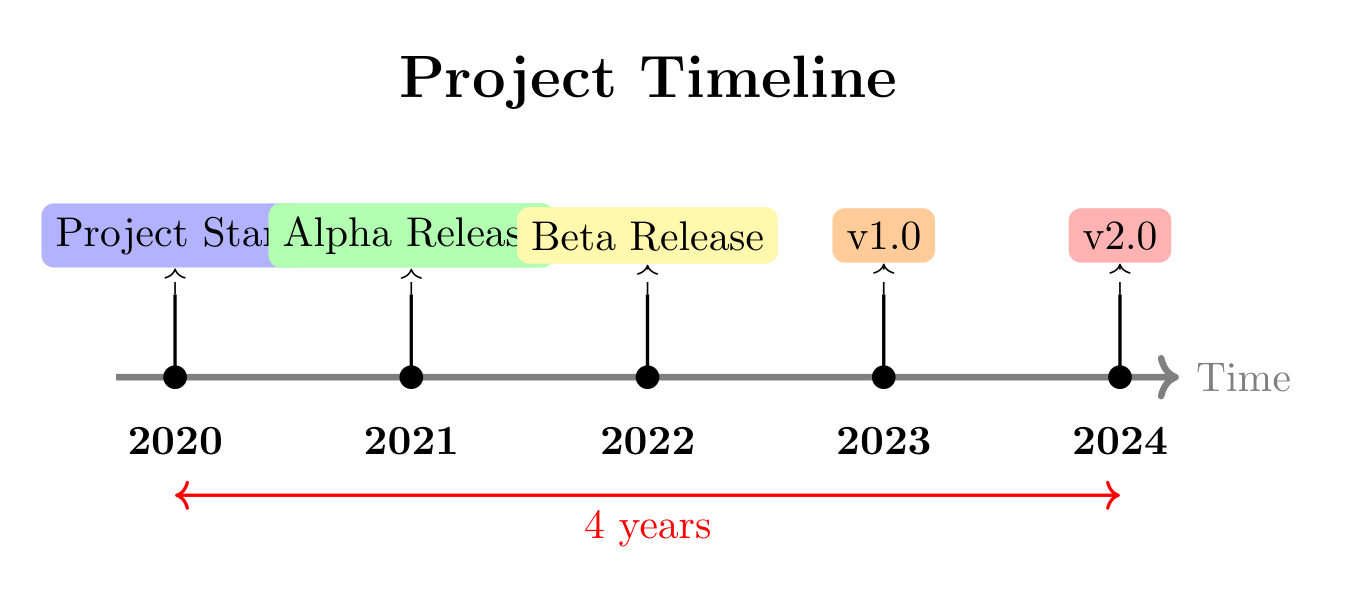
Show the TikZ code
% --------------------------------------------- %% Tikzfigure generated by tikzfigure v0.5.0 %% https://github.com/max-models/tikzfigure %% --------------------------------------------- %\begin{tikzpicture} \draw[->, ultra thick, gray] (-0.5, 0) -- (8.5, 0) node[right] {Time}; \node[rounded corners=3pt, shape=rectangle, fill=blue!30] (node0) at ({0}, {1.2}) {Project Start}; \draw[thick] (0, 0) -- (0, 0.7); \fill (0, 0) circle (0.1); \node[below] at (0, -0.3) {\textbf{2020}}; \draw[->, dashed] (0, 0.7) -- (node0); \node[rounded corners=3pt, shape=rectangle, fill=green!30] (node1) at ({2}, {1.2}) {Alpha Release}; \draw[thick] (2, 0) -- (2, 0.7); \fill (2, 0) circle (0.1); \node[below] at (2, -0.3) {\textbf{2021}}; \draw[->, dashed] (2, 0.7) -- (node1); \node[rounded corners=3pt, shape=rectangle, fill=yellow!40] (node2) at ({4}, {1.2}) {Beta Release}; \draw[thick] (4, 0) -- (4, 0.7); \fill (4, 0) circle (0.1); \node[below] at (4, -0.3) {\textbf{2022}}; \draw[->, dashed] (4, 0.7) -- (node2); \node[rounded corners=3pt, shape=rectangle, fill=orange!40] (node3) at ({6}, {1.2}) {v1.0}; \draw[thick] (6, 0) -- (6, 0.7); \fill (6, 0) circle (0.1); \node[below] at (6, -0.3) {\textbf{2023}}; \draw[->, dashed] (6, 0.7) -- (node3); \node[rounded corners=3pt, shape=rectangle, fill=red!30] (node4) at ({8}, {1.2}) {v2.0}; \draw[thick] (8, 0) -- (8, 0.7); \fill (8, 0) circle (0.1); \node[below] at (8, -0.3) {\textbf{2024}}; \draw[->, dashed] (8, 0.7) -- (node4); \node[font=\Large\bfseries] at (4, 2.5) {Project Timeline}; \draw[<->, red, thick] (0, -1) -- node[below] {4 years} (8, -1);\end{tikzpicture}Show the standalone LaTeX document
\documentclass[border=10pt]{standalone}\PassOptionsToPackage{dvipsnames,svgnames,x11names}{xcolor}\usepackage{tikz}\usepackage{pgfplots}\pgfplotsset{compat=newest}\usepgfplotslibrary{groupplots}\usetikzlibrary{arrows.meta}\begin{document}% --------------------------------------------- %% Tikzfigure generated by tikzfigure v0.5.0     %% https://github.com/max-models/tikzfigure      %% --------------------------------------------- %\begin{tikzpicture}    \draw[->, ultra thick, gray] (-0.5, 0) -- (8.5, 0) node[right] {Time};    \node[rounded corners=3pt, shape=rectangle, fill=blue!30] (node0) at ({0}, {1.2}) {Project Start};    \draw[thick] (0, 0) -- (0, 0.7);    \fill (0, 0) circle (0.1);    \node[below] at (0, -0.3) {\textbf{2020}};    \draw[->, dashed] (0, 0.7) -- (node0);    \node[rounded corners=3pt, shape=rectangle, fill=green!30] (node1) at ({2}, {1.2}) {Alpha Release};    \draw[thick] (2, 0) -- (2, 0.7);    \fill (2, 0) circle (0.1);    \node[below] at (2, -0.3) {\textbf{2021}};    \draw[->, dashed] (2, 0.7) -- (node1);    \node[rounded corners=3pt, shape=rectangle, fill=yellow!40] (node2) at ({4}, {1.2}) {Beta Release};    \draw[thick] (4, 0) -- (4, 0.7);    \fill (4, 0) circle (0.1);    \node[below] at (4, -0.3) {\textbf{2022}};    \draw[->, dashed] (4, 0.7) -- (node2);    \node[rounded corners=3pt, shape=rectangle, fill=orange!40] (node3) at ({6}, {1.2}) {v1.0};    \draw[thick] (6, 0) -- (6, 0.7);    \fill (6, 0) circle (0.1);    \node[below] at (6, -0.3) {\textbf{2023}};    \draw[->, dashed] (6, 0.7) -- (node3);    \node[rounded corners=3pt, shape=rectangle, fill=red!30] (node4) at ({8}, {1.2}) {v2.0};    \draw[thick] (8, 0) -- (8, 0.7);    \fill (8, 0) circle (0.1);    \node[below] at (8, -0.3) {\textbf{2024}};    \draw[->, dashed] (8, 0.7) -- (node4);    \node[font=\Large\bfseries] at (4, 2.5) {Project Timeline};    \draw[<->, red, thick] (0, -1) -- node[below] {4 years} (8, -1);\end{tikzpicture}
\end{document}