The RF field of one and two drivers with a prescribed plasma: mutual coupling and shields.
The geometry of Zielke, Briefi and Fantz (NIBS’22, arXiv:2211.10143, Fig. 2): a
horizontal 2D cut through a driver (23.7 cm wide, 17.4 cm long) and the expansion region
(24.4 cm), six coil windings (6 mm tubes) on each side, 1 MHz; the backplates and the
expansion walls are perfect conductors, and so are the electromagnetic shields (EMS) when
present. With :class:wellbalanced.spatial.InductiveField2D and a prescribed plasma
shaped like their Fig. 3 (up to 1.4e18 m^-3, depleted at the coil), this computes:
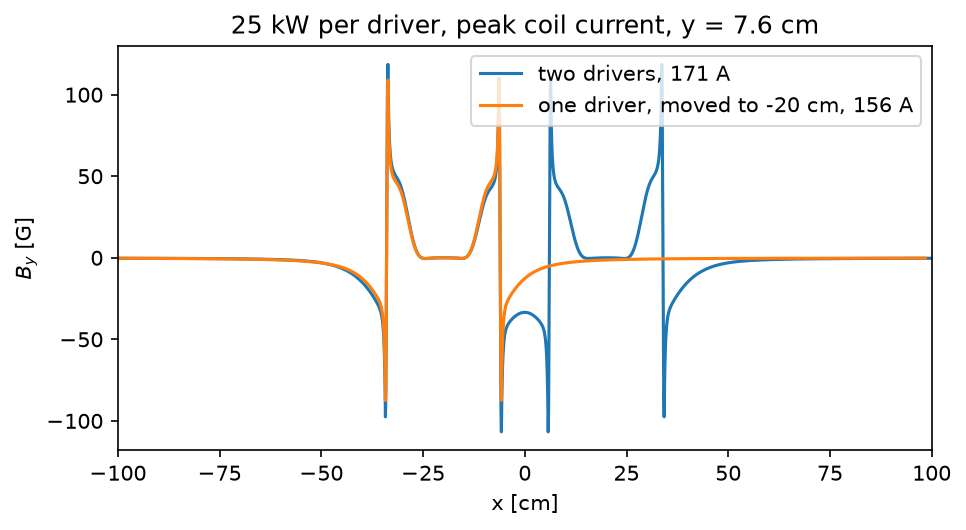
|B_y|along the line through the coil centres, one driver and two (their Fig. 4): the second driver raises the field at the coils;- the coil current for 25 kW absorbed per driver and the RF power transfer efficiency, one driver and two (their 263 A and 284 A, 55 % and 50 %);
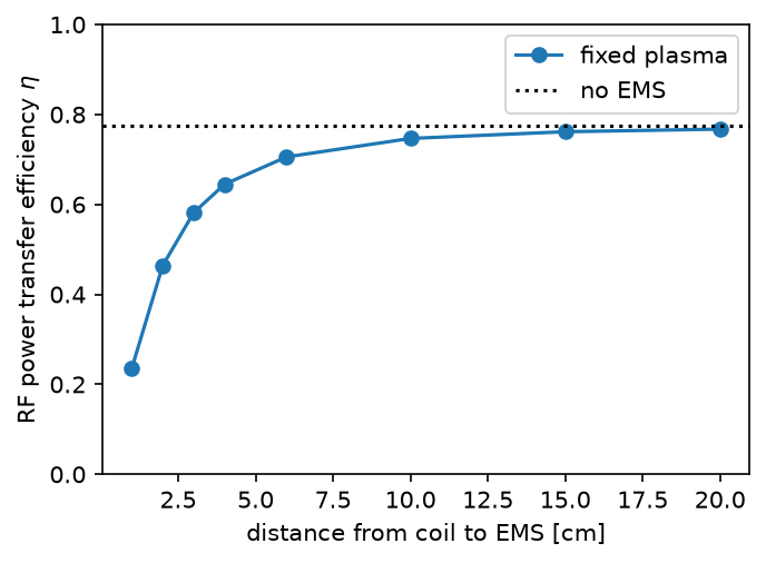
- the efficiency against the distance between the coil and the shield (their Fig. 6).
With the plasma held fixed, only the mechanism and the trends are expected, not the
numbers: the paper’s plasma follows the field (the RF Lorentz force pushes it from the
coil), and its 2D-to-3D conversion is not stated. Here the power of a driver is the power
per unit length of the cut times DEPTH = pi times the driver radius (the half
circumference, where the skin layer is), and the collision frequency is a placeholder of
the right order (1e7 /s, from an e-H2 momentum-transfer cross section of about 1e-19 m^2
at 10 eV on 4.5e19 m^-3 of gas).
Python source
Section titled “Python source”"""The RF field of one and two drivers with a prescribed plasma: mutual coupling and shields.
The geometry of Zielke, Briefi and Fantz (NIBS'22, arXiv:2211.10143, Fig. 2): ahorizontal 2D cut through a driver (23.7 cm wide, 17.4 cm long) and the expansion region(24.4 cm), six coil windings (6 mm tubes) on each side, 1 MHz; the backplates and theexpansion walls are perfect conductors, and so are the electromagnetic shields (EMS) whenpresent. With :class:`wellbalanced.spatial.InductiveField2D` and a *prescribed* plasmashaped like their Fig. 3 (up to 1.4e18 m^-3, depleted at the coil), this computes:
1. ``|B_y|`` along the line through the coil centres, one driver and two (their Fig. 4): the second driver raises the field at the coils;2. the coil current for 25 kW absorbed per driver and the RF power transfer efficiency, one driver and two (their 263 A and 284 A, 55 % and 50 %);3. the efficiency against the distance between the coil and the shield (their Fig. 6).
With the plasma held fixed, only the mechanism and the trends are expected, not thenumbers: the paper's plasma follows the field (the RF Lorentz force pushes it from thecoil), and its 2D-to-3D conversion is not stated. Here the power of a driver is the powerper unit length of the cut times ``DEPTH`` = pi times the driver radius (the halfcircumference, where the skin layer is), and the collision frequency is a placeholder ofthe right order (1e7 /s, from an e-H2 momentum-transfer cross section of about 1e-19 m^2at 10 eV on 4.5e19 m^-3 of gas)."""
import matplotlib.pyplot as pltimport numpy as npfrom simgeometry import Circle, Rectangle
from wellbalanced.spatial import ( Conductor, InductiveField2D, Winding, stretched_edges,)
FREQUENCY = 1.0e6HALF_WIDTH = 0.237 / 2 # driver plasmaDRIVER_LENGTH = 0.174EXPANSION = 0.244COIL_OFFSET = 0.1395 # winding centre from the driver axis: 2.1 cm outside the plasmaTUBE_RADIUS = 0.003WINDING_PITCH = 0.022WALL = 0.01 # backplate and wall thicknessSHIELD = 0.002 # EMS thicknessN_PEAK = 1.4e18COLLISION_FREQUENCY = 1.0e7 # placeholderDEPTH = np.pi * HALF_WIDTHNETWORK_RESISTANCE = 0.6 # per driver, measured at BUGPOWER = 25e3 # absorbed per driverSPACING = 1.0e-3
def box(x0, x1, y0, y1): """A rectangle from its bounds.""" return Rectangle(((x0 + x1) / 2, (y0 + y1) / 2), (x1 - x0, y1 - y0))
def source(centres, expansion_half, shield_distance=None): """The windings, conductors and plasma of drivers at ``centres``.""" windings, conductors = [], [] plate_top = DRIVER_LENGTH - WALL for k, xc in enumerate(centres): for side, sign in ((-1.0, 1.0), (1.0, -1.0)): for n in range(6): y = DRIVER_LENGTH / 2 + (n - 2.5) * WINDING_PITCH windings.append( Winding(Circle((xc + side * COIL_OFFSET, y), TUBE_RADIUS), sign) ) outer = HALF_WIDTH + 0.006 # the dielectric driver wall conductors.append( Conductor( [box(xc - outer, xc + outer, -WALL, 0.0)], name=f"driver backplate {k}" ) ) if shield_distance is not None: plates = [ box(x - SHIELD / 2, x + SHIELD / 2, -WALL, plate_top) for x in ( xc - COIL_OFFSET - shield_distance, xc + COIL_OFFSET + shield_distance, ) ] conductors.append(Conductor(plates, name=f"shield {k}")) # the source backplate around the driver openings, the expansion walls and grid openings = sorted( (xc - HALF_WIDTH - 0.006, xc + HALF_WIDTH + 0.006) for xc in centres ) edges = [-expansion_half, *[x for pair in openings for x in pair], expansion_half] pieces = [ box(edges[i], edges[i + 1], plate_top, DRIVER_LENGTH) for i in range(0, len(edges), 2) if edges[i + 1] > edges[i] ] top = DRIVER_LENGTH + EXPANSION pieces += [ box(-expansion_half - WALL, -expansion_half, plate_top, top + WALL), box(expansion_half, expansion_half + WALL, plate_top, top + WALL), box(-expansion_half, expansion_half, top, top + WALL), ] conductors.append(Conductor(pieces, name="source"))
def density(x, y): n = np.zeros_like(x) for xc in centres: inside = (np.abs(x - xc) < HALF_WIDTH) & (y > 0.0) & (y < DRIVER_LENGTH) radial = np.cos(0.5 * np.pi * (x - xc) / HALF_WIDTH) ** 2 axial = 0.35 + 0.65 * np.sin(0.5 * np.pi * np.minimum(y / 0.15, 1.0)) n = np.where(inside, N_PEAK * radial * axial, n) lobes = sum( np.cos(0.5 * np.pi * (x - xc) / (HALF_WIDTH + 0.05)) ** 2 * (np.abs(x - xc) < HALF_WIDTH + 0.05) for xc in centres ) expansion = (np.abs(x) < expansion_half) & (y >= DRIVER_LENGTH) & (y < top) decay = np.exp(-(y - DRIVER_LENGTH) / 0.12) return np.where(expansion, N_PEAK * (0.15 + 0.6 * lobes * decay), n)
return windings, conductors, density
def model(centres, expansion_half, shield_distance=None, fine_half=0.36): """The field model, 1 mm cells over the source, stretched to a 2.4 m box.""" windings, conductors, density = source(centres, expansion_half, shield_distance) x_edges = stretched_edges(-1.2, 1.2, -fine_half, fine_half, SPACING, ratio=1.06) y_edges = stretched_edges(-0.8, 1.2, -0.03, 0.44, SPACING, ratio=1.06) return InductiveField2D( x_edges, y_edges, frequency=FREQUENCY, windings=windings, conductors=conductors, electron_density=density, collision_frequency=COLLISION_FREQUENCY, )
def at_power(field_model, drivers): """The solution with ``POWER`` absorbed per driver, its efficiency and |B_y|.""" solution = field_model.solve(1.0).for_power(drivers * POWER, DEPTH) eta = solution.efficiency(drivers * NETWORK_RESISTANCE, DEPTH) return solution, eta
single = model([0.0], 0.16)double = model([-0.20, 0.20], 0.43, fine_half=0.47)one, eta_one = at_power(single, 1)two, eta_two = at_power(double, 2)print(" this model (fixed plasma) Zielke et al. (self-consistent)")print(f"coil current, 1 driver {abs(one.coil_current):6.0f} A 263 A")print(f"coil current, 2 drivers {abs(two.coil_current):6.0f} A 284 A")print(f"efficiency, 1 driver {eta_one:6.1%} 55 %")print(f"efficiency, 2 drivers {eta_two:6.1%} 50 %")print( f"plasma resistance per driver: {one.plasma_resistance(DEPTH):.3f} Ohm (1), " f"{two.plasma_resistance(DEPTH) / 2:.3f} Ohm (2)")
# 1. B_y along a row of winding centres at peak coil current (Fig. 4)y_row = DRIVER_LENGTH / 2 - 0.5 * WINDING_PITCH # the third winding from the bottom
def field_on_row(solution, shift=0.0): """The x coordinates and the instant B_y at peak coil current on the winding row.""" j = np.argmin(np.abs(solution.y - y_row)) _, b_y = solution.magnetic_field return (solution.x + shift), np.real(b_y[:, j]) # the instant of peak current
fig, ax = plt.subplots(figsize=(7, 3.5))for solution, label, shift in ( (two, "two drivers", 0.0), (one, "one driver, moved to -20 cm", -0.20),): x, b = field_on_row(solution, shift) ax.plot(x * 100, b * 1e4, label=f"{label}, {abs(solution.coil_current):.0f} A")ax.set_xlim(-100, 100)ax.set_xlabel("x [cm]")ax.set_ylabel("$B_y$ [G]")ax.set_title(f"25 kW per driver, peak coil current, y = {y_row * 100:.1f} cm")ax.legend()# the coupling at the same coil current: the field just inside the gap between the# drivers, beside the left driver's inner coil (x = -6 cm), against the single driverinner_coil = -0.20 + COIL_OFFSETfor solution, name, shift in ( (one.scaled(1.0), "one driver", -0.20), (two.scaled(1.0), "two drivers", 0.0),): x, b = field_on_row(solution, shift) beside = (x > inner_coil + TUBE_RADIUS) & (x < inner_coil + 3 * TUBE_RADIUS) print( f"B_y beside the inner coil per A of coil current, {name}: " f"{np.abs(b[beside]).max() * 1e4:.3f} G/A" )
# 2. the efficiency against the coil-shield distance (Fig. 6), one driverdistances = np.array([0.01, 0.02, 0.03, 0.04, 0.06, 0.10, 0.15, 0.20])efficiencies = []for distance in distances: shielded = model([0.0], 0.16, shield_distance=distance) efficiencies.append(at_power(shielded, 1)[1])print("coil-EMS distance [cm]: " + " ".join(f"{d * 100:5.0f}" for d in distances))print("efficiency, this model: " + " ".join(f"{e:5.2f}" for e in efficiencies))print( "Zielke et al. Fig. 6: 0.21 0.31 0.41 0.46 0.50 0.54 0.54 0.54 (read off)")print(f"no EMS: {eta_one:.2f} (Zielke: 0.55)")fig, ax = plt.subplots(figsize=(5, 3.5))ax.plot(distances * 100, efficiencies, "o-", label="fixed plasma")ax.axhline(eta_one, color="k", ls=":", label="no EMS")ax.set_xlabel("distance from coil to EMS [cm]")ax.set_ylabel(r"RF power transfer efficiency $\eta$")ax.set_ylim(0, 1)ax.legend()
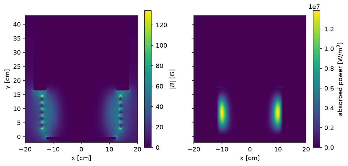
# the field and the absorbed power of one driverfig, axes = plt.subplots(1, 2, figsize=(9, 4), sharey=True)b_x, b_y = one.magnetic_fieldwindow = (np.abs(one.x) < 0.2)[:, None] & ((one.y > -0.02) & (one.y < 0.43))[None, :]xs, ys = one.x[np.abs(one.x) < 0.2], one.y[(one.y > -0.02) & (one.y < 0.43)]shape = (xs.size, ys.size)for ax, values, title in ( (axes[0], np.hypot(np.abs(b_x), np.abs(b_y)), "$|B|$ [G]"), (axes[1], one.power_density, "absorbed power [W/m$^3$]"),): data = values[window].reshape(shape).T image = ax.pcolormesh(xs * 100, ys * 100, data * (1e4 if "G" in title else 1.0)) fig.colorbar(image, ax=ax, label=title) ax.set_xlabel("x [cm]") ax.set_aspect("equal")axes[0].set_ylabel("y [cm]")